


 See Also
 Important: Important: |
|---|
| This is retired content. This content is outdated and is no longer being maintained. It is provided as a courtesy for individuals who are still using these technologies. This content may contain URLs that were valid when originally published, but now link to sites or pages that no longer exist. |
Conceptually, a viewport is a 2-D rectangle into which a three-dimensional scene is projected. In Microsoft® Direct3D® Mobile, the rectangle exists as coordinates within a Direct3D Mobile surface that the system uses as a rendering target. The projection transformation converts vertices into the coordinate system used for the viewport.
You use a viewport in Direct3D Mobile to specify the following features in your application:
- The screen-space viewport to which the rendering will be
confined.
- The range of depth values on a render-target surface into which
a scene will be rendered (usually 0.0 to 1.0).
The viewport transformation is the final transformation from projection space to homogeneous screen space. The viewport transformation scales coordinates to be within the viewport window and Z range, and it inverts the Y axis.
 Viewport Rectangle
Unlike other transformations, the viewport transformation is not specified by a matrix. You define the viewport rectangle by using the D3DMVIEWPORTstructure. The D3DMVIEWPORTstructure is used with the following viewport manipulation methods exposed by the IDirect3DMobileDeviceinterface:
The D3DMVIEWPORTstructure contains four members — X, Y, Width, and Height— that define the area of the render-target surface into which a scene will be rendered. These values correspond to the destination rectangle, or viewport rectangle, as shown in the following illustration.
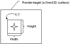
The values you specify for the X, Y, Width, and Heightmembers of the D3DMVIEWPORTstructure are screen coordinates relative to the upper-left corner of the render-target surface. The structure defines two additional members ( MinZand MaxZ) that indicate the depth-ranges into which the scene will be rendered.
Direct3D Mobile assumes that the viewport clipping volume ranges from -1.0 to 1.0 in X, and from 1.0 to -1.0 in Y. These were the settings used most often by applications in the past. During the projection transformation, you can adjust for viewport aspect ratio before clipping. For more information, see Projection Transformations.
 Note: Note: |
|---|
| The D3DMVIEWPORTstructure members MinZand MaxZindicate the depth-ranges into which the scene will be rendered and are not used for clipping. Most applications will set these members to 0.0 and 1.0 to enable the system to render to the entire range of depth values in the depth buffer. In some cases, you can achieve special effects by using other depth ranges. For instance, to render a heads-up display in a game, you can set both values to 0.0 to force the system to render objects in a scene in the foreground, or you might set them both to 1.0 to render an object that should always be in the background. |
Viewport Scaling
The dimensions used in the X, Y, Width, and Heightmembers of the D3DMVIEWPORTstructure for a viewport define the location and dimensions of the viewport on the render-target surface. These values are in screen coordinates, relative to the upper-left corner of the surface.
Direct3D Mobile uses the viewport location and dimensions to scale the vertices to fit a rendered scene into the appropriate location on the target surface. Internally, Direct3D Mobile inserts these values into a matrix that is applied to each vertex.

This matrix simply scales vertices according to the viewport dimensions and desired depth range and translates them to the appropriate location on the render-target surface. The matrix also flips the y-coordinate to reflect a screen origin at the top-left corner with y increasing downward. After this matrix is applied, vertices are still homogeneous — that is, they still exist as [x,y,z,w] vertices — and they must be converted to non-homogeneous coordinates before being sent to the rasterizer. This is performed by way of simple division, as discussed in Rasterization.