 Important: Important: |
|---|
| This is retired content. This content is outdated and is no longer being maintained. It is provided as a courtesy for individuals who are still using these technologies. This content may contain URLs that were valid when originally published, but now link to sites or pages that no longer exist. |
Microsoft Corporation
April 2000
Summary:This paper provides a brief introduction to Universal Serial Bus (USB) technology, an overview of the USB support present in Windows CE 2.10, and an overview of how to write USB device drivers for Windows CE 2.10. (9 printed pages)
Contents
Introduction
As its name suggests, Universal Serial Bus (USB) is an external
bus architecture for connecting USB-capable peripheral devices to a
host computer. USB was not designed to be used as the internal bus
for connecting CPUs to main memory and other motherboard-resident
devices. Instead, USB is a communication protocol that supports
serial data transfers between a host system and USB-capable
peripherals. USB technology was developed as a solution to the
increasing end-user demands on computers and the need for flexible
and easy-to-use peripherals. A number of standard PC peripherals
such as keyboards, mice, joysticks, digital cameras, CTI (computer
telephone integration) and Video conferencing products benefit
directly from USB. USB offers a number of benefits to system designers:
Note that the official Universal Serial Bus Specification uses
the term
functionto refer to USB-capable peripheral devices. To avoid
any confusion with the term
functionas it refers to callable units of C/C++ code, the
Windows CE documentation set will use the term
USB deviceinstead. This section provides a brief overview of the organization of
the Universal Serial Bus itself and of the software that must be
present on the host computer. A USB system is composed of a host side, a device side, and the
physical bus represented by the USB cable. The main responsibility
of the host is to provide a control interface for data transfers
whereas the device side provides the end user with various
functions. The host side itself consists of a USB adapter or USB
host controller hardware layer and an upper-level System Software
layer. The host controller is responsible for transferring streams
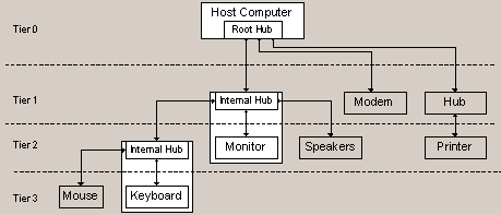
of data between the host and the USB devices. USB is a tree-structured bus, which in the vocabulary of the USB
developers organization is called a
Star-Tier topology. The host computer contains the root node
of the bus, which is called a
hub. Any node within a USB bus that is an intermediary
between peripheral devices and the host computer is a hub. A hub
has exactly one connection to higher levels in the USB bus than
itself (an
upstream port, and can have up to 7 ports for connecting
peripheral devices and other hubs. Up to 127 devices can be
connected in this manner. Peripheral devices are always leaf nodes
within a USB bus. However, as a matter of practical implementation,
many USB peripheral devices have a hub integrated into them so that
users do not often have to purchase separate USB hubs. The following illustration shows a typical USB bus with several
common peripherals connected. This illustration is modeled after
the diagram of a typical USB bus configuration in the Universal
Serial Bus Specification, Revision 1.0, but with the hubs and
peripheral devices represented more explicitly:
Figure 1. Typical USB bus with several common peripherals
connected
Note that the association of the mouse with the keyboard's
internal hub and the speakers with the monitor's internal hub is
entirely arbitrary. For example, a user could instead connect the
mouse to the monitor's internal hub, the modem to the keyboard's
internal hub, and the speakers to the standalone hub in tier 1
without impacting the system's functionality and without having to
make any changes to the configuration of software on the host
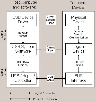
computer. As illustrated in the diagram below, a USB system consists of a
host side, a device side, and the physical bus represented by the
USB cable. The main responsibility of the host is to provide
control interface for data transfers whereas the client provides
the end user with various functions. The host side itself consists
of a USB adapter or USB Host Controller hardware layer and an
upper-level System Software layer. The host controller is
responsible for transferring streams of data between the host and
the USB devices. The host controller provides services based on
parameters provided by the host software when the configuration
request is made. The system software for USB consists of two layers. The top
layer consists of USB device drivers. Such drivers establish a
connection to the device they control and use the USB system
software functions to configure and communicate with the
device. The bottom layer consists of the USB system software. This
software performs several tasks:
The USB system software is itself composed of two major parts,
the upper Universal Serial Bus Driver (USBD) module, and the lower
Host Controller Driver (HCD) module. The USBD module implements the
high-level USB functions that USB device drivers use in terms of
the functionality provided by the HCD module. The HCD module
interfaces between the particular USB host controller hardware
(such as OHCI or UHCI adapters) and the USBD module. IHVs and manufacturers of USB devices will be concerned with the
top layer, since they will need to provide device drivers for their
USB devices for any operating systems on which their USB devices
will be used. OEMs will be primarily concerned with the bottom
layer, since they will need to ensure that their Windows CE
platform's hardware properly interfaces with the USBD module. The following illustration shows these two layers of software in
the context of the host's USB hardware and a peripheral device:
Figure 2. Top and bottom layers of software in relation to the
host's USB hardware and peripherals
The flow of operation is typically:
Note that all transactions on the bus originate from the host
side; the peripherals perform only as slaves in this master-slave
environment. USB devices consist of one or more
interfaces, which are the physical components of the
peripheral that implement the device's abilities. Associated with
each interface is a set of endpoints; endpoints are the ultimate
producers or consumers of data that travels across the bus. In
addition, all USB devices have a special endpoint, known as
endpoint 0, which supports the generic USB status and
configuration protocol. Every device known to the HCD module has a
unique USB address assigned to it when it is attached. USB device drivers establish logical communication channels,
called
pipesto the various endpoints on a USB device. The
characteristics of a pipe, that is direction of communication,
required bandwidth, and so on, are determined by the endpoint
characteristics, which are indicated in the endpoint descriptor
structure. A pipe is a software association between an endpoint and
a USB device driver. At implementation level, pipes can be thought
of as software channels using function calls within the USB system
software in order to communicate with their associated
endpoints. The bus interface hardware on a USB device is responsible for
transmission and reception of USB structured data. A logical USB
device consists of the USB abstraction entities such as the device
endpoints and their corresponding pipes. An interface is a higher-level entity that consists of one or
more pipes and corresponds to some useful unit of functionality for
the host computer. For example, a haptic input device such as a
force-feedback joystick, could have separate pipes for the position
information that the joystick sends to the host computer and the
force-feedback information that the host computer sends to the
joystick. Taken together, that collection of pipes is known as an
interface because it corresponds to the joystick as a whole. An
interface can be controlled by exactly one USB device driver. This section describes the different components of USB support
for Windows CE 2.10. Note that the primary focus of USB support in
Windows CE has been to enable the technology such that OEMs can
expand on this support. To this end, Windows CE supports only the
host side of USB. In essence, Microsoft provides the USB system
software and a sample mouse driver that uses it. Microsoft supplies the following USB software components:
Source code for these components is available in the
\wince\public\common\oak\drivers\usb directory in the Windows CE
Embedded Toolkit. Header files are in the public\oak\inc and
public\ddk\inc directory, and platform sample code is in the
platform\cepc\drivers\usb directory.
Bus Enumeration.Windows CE supports enumeration of USB
devices on the bus. The bus enumeration process consists of an
interrogation sequence through which the HCD module acquires
information from a connected device, assigns it a unique USB
address, and sets a configuration value. This a multi-step process.
Once the enumeration is completed, the device is configured and
ready to conduct transmit and receive transactions. At this point,
the USBD module will attempt to load one or more client drivers to
control the device, based on the information contained in the
device and interface descriptors. If no suitable driver has been
registered for the device, the user is prompted to enter the name
of a driver to control the device.
Power Management.When Windows CE issues a POWER_DOWN
notification, the USB host controller hardware and all devices are
suspended by the system. At the following POWER_UP notification,
the USB host controller hardware is reinitialized, the USBD module
unloads the client drivers for all the devices, enumerates the USB
devices connected to the bus and loads the drivers for those
devices. Windows CE also provides support for bus-powered and
self-powered devices. For both types of devices, the USBD module
reads the power requirements of the device from the descriptor
information, and rejects the device if the maximum power threshold
is exceeded. OEMs can set this current-draw limit through a
registry entry.
Hub Support.Windows CE supports connecting hub devices up to
one level deep. Thus, referring back to the earlier diagram of a
typical USB configuration, hubs can only be connected in Tier 1,
and peripheral devices can only be connected in Tiers 1 and 2. Windows CE 2.10 supports all four types of data transfers as
required by the Universal Serial Bus Specification, Revision 1.0,
to support a variety of devices. Device drivers for USB devices can
use any of these transfer types that may be appropriate for the
device:
There is no support in Windows CE 2.10 for making the Windows CE
platform itself appear as an USB peripheral to other host
computers. That is, we do not provide any Function Drivers on the
host or device side to connect a Windows CE platform (such as an
HPC) to a desktop computer running a USB host. Windows CE 2.10 does not provide any Class Drivers for classes
of devices. Examples of class devices include the Human Input
Device (HID) class, Stream Class, and so on. However, class drivers
are supported by the USB system software, so OEMs can write their
own HID class drivers to support HID class devices, and load them
appropriately using the registry mechanism. Microsoft will not provide a wide range of drivers for USB
devices in Windows CE 2.10. If an OEM wishes to support a
particular USB device, then they will be responsible for writing a
USB device driver to interface with the USBD module. A UHCI driver will not be included with Windows CE 2.10, but
OEMs can write their own UHCI driver that uses and conforms to the
USBD to HCD interface. This section describes sequence of actions that takes place when
USB drivers are loaded, the required entry points for all USB
drivers, and briefly discusses the sample USB mouse driver included
with Windows CE 2.10. Note that this section does not provided
details on writing USB device drivers; that information is beyond
the scope of this document and can be found in the Windows CE
Device Driver Kit. Similar to PCMCIA drivers, USB drivers are loaded via the
registry mechanism. The USBD module is responsible for loading USB
client drivers when a USB device is attached. The USBD module uses
the HKEY_LOCAL_MACHINE\Drivers\LoadClients portion of the registry
on the platform to identify the appropriate USB driver for a given
device. The algorithm used by the USBD module to identify the
appropriate USB device driver from the information in the registry
is complex; full details are documented in the Windows CE Device
Driver Kit. Note that the LoadClients registry key must be set up
correctly such that your USB device driver will be loaded for your
USB device; each installed USB device driver must have such a key
in order to be recognized and loaded by the USBD module. The load strategy used by the USBD module provides a flexible
framework that allows USB device drivers to be registered in
different ways, depending on the scope of devices that they wish to
control. For example:
All USB device drivers must expose a certain number of the
following entry points in their DLL. These entry points will allow
them to configure and setup the device connected on the bus or set
up the registry.
USBDeviceAttach.This entry point called when the USB device
for some USB device driver is connected to the USB bus. The
driver's implementation of this function can decline to control the
device, in which case Windows CE will attempt to find another
driver to handle the device.
USBInstallDriver.This entry point is called the first time
that the USB device driver is loaded, and gives the driver a chance
to create any registry keys that it needs.
USBUnInstallDriver.This is called when the user removes the
driver from his or her Windows CE platform. This entry point is
responsible for removing all registry keys created by the driver's
USBInstallDriver function and releasing any other resources held by
the driver. Full details about the syntax of these entry points can be found
in the Windows CE Device Driver Kit. The Embedded Toolkit for Windows CE 2.10 contains source code
for a sample driver for USB mouse devices. This driver uses
interrupt-driven transfers. OEMs and IHVs are encouraged to use the
mouse sample driver source code as the basis for other USB device
drivers. Note that the registry is already set up correctly for the
sample CE/PC platform to load the mouse driver, so that plugging in
a mouse should load the driver. There is no extensive USB test suite for Windows CE at this
time. The sample USB mouse driver, the USB CD-Changer device driver
for the Auto PC and the USB 8x930Ax peripheral kit and evaluation
board from Intel Corporation can be used to assist in testing USB
scenarios. These same methods were used at Microsoft to test the
USB system software for Windows CE 2.10. Further details on testing
a USB system and the device drivers on an OEM platform are
available in the Windows CE Embedded Toolkit. The
USB
Implementers Forum home pagecontains the complete USB
specification, Universal Serial Bus Specification, Revision 1.0.
Anyone considering building a USB compatible device or designing a
hardware platform that supports USB should read this
specification. The
Intel
Web siteprovides information on USB hardware and
microcontroller chips, such as the 8x930Ax and 8x931xA series
chips. The Windows CE Device Driver Kit contains complete information
on writing device drivers for Windows CE.
USB System Architecture
USB Support in Windows CE 2.1
For More Information
Introduction
USB System Architecture
Bus Topology
System Software
USB Devices
USB Support in Windows CE 2.1
Microsoft-Supplied Components
System Software Support
Support for Transfer Types:
Unsupported Features
Device Drivers for USB Devices
USB driver load process
Required entry points for USB device drivers
Sample USB Mouse Driver
Testing USB Device Drivers
For More Information