![]()
![]()
|
|
|
|
20.41 - 27.22 kg 47.18 - 60.0 lb |
WARNING: To reduce the risk of personal injury or damage to the equipment:
|
 NOTE: If the cable
management arm is mounted on the right side of the rack, you will
have to remove it when adding or replacing a redundant hot-plug
power supply.
NOTE: If the cable
management arm is mounted on the right side of the rack, you will
have to remove it when adding or replacing a redundant hot-plug
power supply.
 WARNING: To reduce the risk of electric
shock, fire, or damage to the equipment, do not plug telephone or
telecommunications connectors into RJ-45
connectors.
WARNING: To reduce the risk of electric
shock, fire, or damage to the equipment, do not plug telephone or
telecommunications connectors into RJ-45
connectors.
 IMPORTANT: If the
RILOE II board is
installed in the server, be sure that you attach the video cable to
the video connector on the rear of the RILOE II board. The standard
video connector on the server rear panel is not used when the RILOE
II board is installed. For more information, refer to the
HP Remote Insight Lights-Out Edition II User
Guide.
IMPORTANT: If the
RILOE II board is
installed in the server, be sure that you attach the video cable to
the video connector on the rear of the RILOE II board. The standard
video connector on the server rear panel is not used when the RILOE
II board is installed. For more information, refer to the
HP Remote Insight Lights-Out Edition II User
Guide.
|
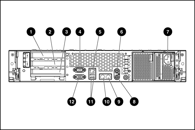
Item |
Description |
Connector color |
|---|---|---|
|
1 |
PCI-X expansion slot 1, 64 bit/100 MHz, Bus A |
N/A |
|
2 |
PCI-X expansion slot 2, 64 bit/100 MHz, Bus A |
N/A |
|
3 |
PCI-X expansion slot 3, 64 bit/133 MHz, Bus B |
N/A |
|
4 |
Serial connector |
Teal |
|
5 |
iLO connector |
N/A |
|
6 |
Mouse connector |
Green |
|
7 |
Power cord connector |
N/A |
|
8 |
Keyboard connector |
Purple |
|
9 |
NIC 1 connector |
N/A |
|
10 |
NIC 2 connector |
N/A |
|
11 |
USB connectors (2) |
Black |
|
12 |
Video connector |
Blue |

NOTE: Peripheral
device cables are removed for clarity.
NOTE: If using the
power cord anchor, be sure to leave enough slack in the power cord
so that the redundant power supply can be removed without
disconnecting the power cord from the primary power
supply.
IMPORTANT: When using
cable management arm components, be sure to leave enough slack in
each of the cables to prevent damage to the cables when the server
is extended from the rack.
WARNING: To reduce the risk of electric
shock or damage to the equipment:
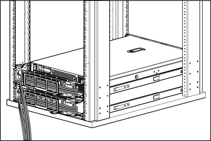
 CAUTION: Always plan
the rack installation so that the heaviest item is on the bottom of
the rack. Install the heaviest item first, and continue to populate
the rack from the bottom to the top.
CAUTION: Always plan
the rack installation so that the heaviest item is on the bottom of
the rack. Install the heaviest item first, and continue to populate
the rack from the bottom to the top.