


 Important: Important: |
|---|
| This is retired content. This content is outdated and is no longer being maintained. It is provided as a courtesy for individuals who are still using these technologies. This content may contain URLs that were valid when originally published, but now link to sites or pages that no longer exist. |
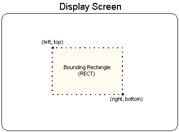
Throughout DirectDraw and Windows Embedded CE programming, objects on the screen are referred to in terms of bounding rectangles.
The sides of a bounding rectangle are always parallel to the sides of the screen, so two points, the top-left corner and bottom-right corner, can describe the rectangle.
Most applications use the RECTstructure to carry information about a bounding rectangle to use when blitting to the screen or performing hit detection. The RECTstructure has the following definition.
 Copy Code Copy Code
|
|
|---|---|
typedef struct tagRECT {
	LONG	left; // This is the top-left corner's x-coordinate.
	LONG	top;  // The top-left corner's y-coordinate.
	LONG	right;   // The bottom-right corner's x-coordinate.
	LONG	bottom;  // The bottom-right corner's y-coordinate.
} RECT, *PRECT, NEAR *NPRECT, FAR *LPRECT;
|
|
In the preceding example, the leftand topmembers are the x- and y-coordinates of a bounding rectangle's top-left corner. Similarly, the rightand bottommembers make up the coordinates of the bottom-right corner.
 Note: Note: |
|---|
| The right and bottom values for all rectangles in Windows Embedded CE are exclusive. Thus if you want a 100x100 square rectangle with the top-left corner at (10,10), the rectangle would be defined as (10,10,110,110). |
The following illustrate shows how you can visualize these values.
In the interest of efficiency, consistency, and ease of use, all DirectDraw blitting functions work with rectangles. However, you can create the illusion of nonrectangular blit operations by using either transparent or alpha blitting. For more information, see Transparent Blittingor Alpha Blitting.